


Heatmiser neoAir V3 Smart Thermostat & RF Switch
Description
Description
Upgrade your heating and hot water control with the Heatmiser neoAir V3 Smart Thermostat & RF Switch. This smart combination offers a convenient and efficient way to manage your home's temperature from anywhere when paired with the Neohub.
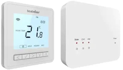
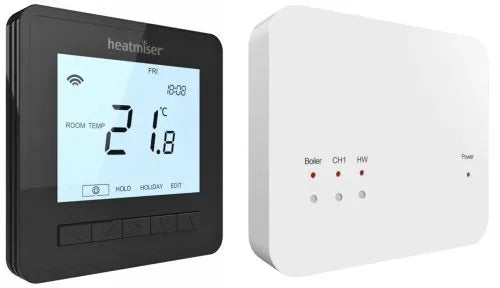
Heatmiser neoAir V3 Smart Thermostat
The Heatmiser neoAir V3 is a battery-powered thermostat that seamlessly integrates with the Heatmiser RF Switch and UH8-RF Wireless Receivers. It provides versatile control options, functioning as a standalone thermostat, a timer, or a combination of both, allowing you to effectively manage your heating and hot water systems.
Key Features:
- Self Learning Preheat: The neoAir V3 utilizes Self Learning Preheat technology to calculate the optimal heat-up time, ensuring your home is warm and comfortable when you wake up or return home. It continuously optimizes these times throughout the year, saving you money and adapting to any changes in your home that may affect the preheat time.
- Mesh Networking: The neoAir V3 communicates wirelessly with the neoHub, creating a reliable and scalable network system. The mains-powered neoStat serves as a signal repeater, extending the communication range between devices. If there are no neoStat devices installed, the neoAir communicates directly with the neoHub. You can also use the neoPlug or Boost to further extend the communication distance.
- Easy Navigation: The neoAir V3 features an intuitive programming system, with all options conveniently displayed on the backlit screen for easy navigation and control.
- Battery Powered: The neoAir V3 operates on batteries, providing flexibility in thermostat placement without the need for wiring.
- Backlit Display: The backlit display ensures clear visibility of temperature and settings, even in low-light environments.
- Programmable Options: Choose from 5/2-day, 7-day, and 24-hour programming modes to create customized heating and hot water schedules based on your daily routines.
- Additional Features: The neoAir V3 also includes a holiday function, temperature hold, air sensor connection, floor sensing mode for precise temperature control, wireless switching to UH8-RF or RF Switch, frost protection, Celsius/Fahrenheit selectable display, and 4 comfort levels per day.
Heatmiser RF Switch
The Heatmiser RF Switch is a surface mount 2-channel wireless receiver designed for controlling 2 heating zones and 1 hot water zone. It provides a volt-free output for the boiler, allowing seamless integration with your heating system.
Pairing the RF Switch with the UH8-RF enables wireless communication with the boiler, enhancing the convenience and flexibility of your heating control.
Elevate your home's heating and hot water control with the Heatmiser neoAir V3 Smart Thermostat & RF Switch combination, and experience comfort and efficiency like never before.
Specifications
| Supply | 4 x AAA Batteries |
|---|---|
| Dimensions (L,H,D) | 86x86x26mm |
| Temperature Range | 05-35C |
| No. Heating Levels | 4 |
| Max Current | 3A |
| IP Rating | IP20 |
| Compatibility | Slimline-RF Touch-RF neoAir UH8-RF |
|---|---|
| no. Of Heating Zones | 2 |
| no. Of Hot Water Zones | 1 |
| Boiler Output | 1 |
| Mounting Type | Surface |
| Relay Load Max | 3a Resistive |
| Total Load Max | 9a Resistive |
| Supply | 230v Ac |
| Dimensions (l,h,d) | 108x90x24mm |
Installation
Heatmiser neoAir
- Carefully separate the front half of the thermostat from the back plate by placing a small flat head terminal driver into the slots on the bottom face of the thermostat.
- Mark 2 hole positions on the wall using the back plate as a positioning template.Drill at the marked positions and insert a wall plug into each hole.
- Screw the thermostat back plate securely on the wall.
- Clip the front of the thermostat back onto the thermostat back plate.
Important Do not install near to a direct heat source as this will affect functionality.
Important Do not push hard on the LCD screen as this may cause irreparable damage.
This wireless thermostat is designed to be surface mounted
Heatmiser RF-Switch
- Using a small screwdriver, slightly loosen the screw located at the base of the RF-Switch. You can then carefully separate the front panel from the back plate.
- Position the RF-Switch back plate on the wall, fixing into place using the screws provided.
- Terminate the cables to the RF-Switch as shown in the wiring diagram.
- Mount the front panel onto the back plate, tighten the retaining screw on the base.
- Switch on the power supply, the power LED will illuminate.
Reviews
Reviews
Payment & Security
Payment methods
Your payment information is processed securely. We do not store credit card details nor have access to your credit card information.
Not sure where to start? Let us help!
Answer a few questions and we’ll get you on your way


